

Category: Motors
How to determine your centre to centre distance when working with motors

When you add a motor you need to transfer the motion. There are a number of ways to do this. Some basic tips will help you understand the process here.
Gears
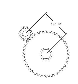
The gears we use are 20 dp. To determine the centre use the Gear calculator that West Coast Products provides. You will need to count the number of teeth on each gear.
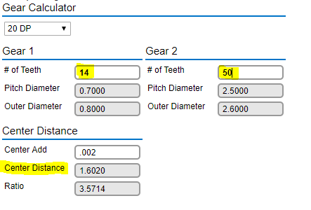
The Center Distance is the distance you want to mount your gears at. Keep in mind – how will you mount your motor so that it doesn’t interfere with your wheel!
Chain and Sprocket
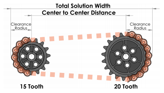
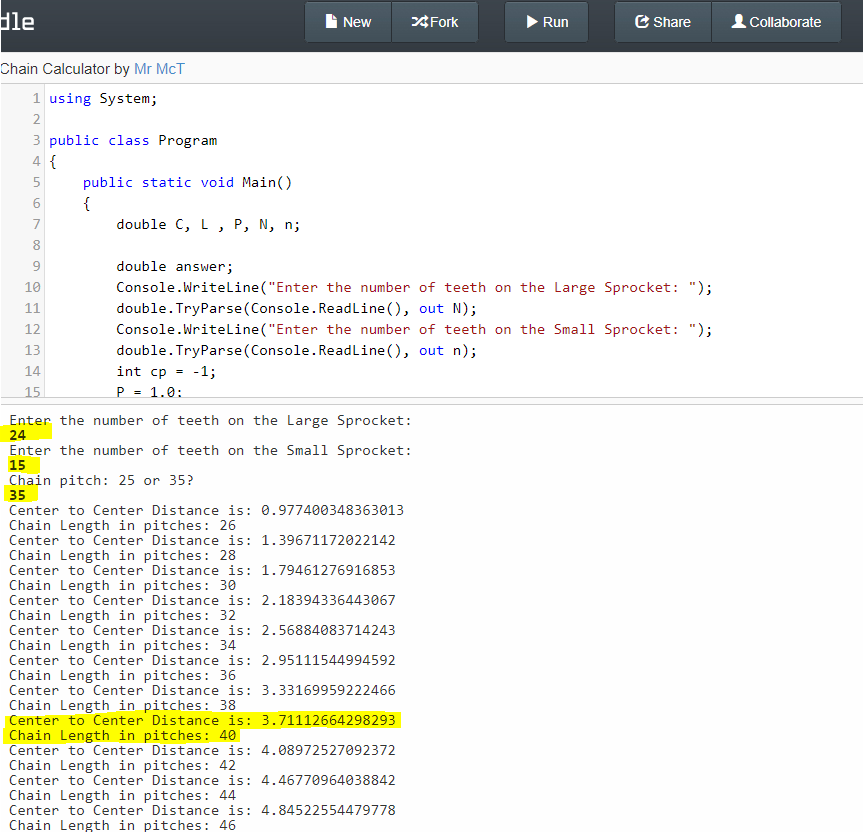
Rev Robotics has a great Chain and Sprocket guide. To make it easier to calculate the centre to centre distance to mount the sprockets I’ve created a program you can use. https://dotnetfiddle.net/rK2yF9 you need to enter the number of teeth for each sprocket and the chain pitch (use 35 as we will be using #35 in class. You will get a number of results. Pick one that will allow you to mount the sprockets so they don’t overlap. You will probably need to break the chain and connect the correct amount of links. Vex Robotics has a great guide on how to do that.
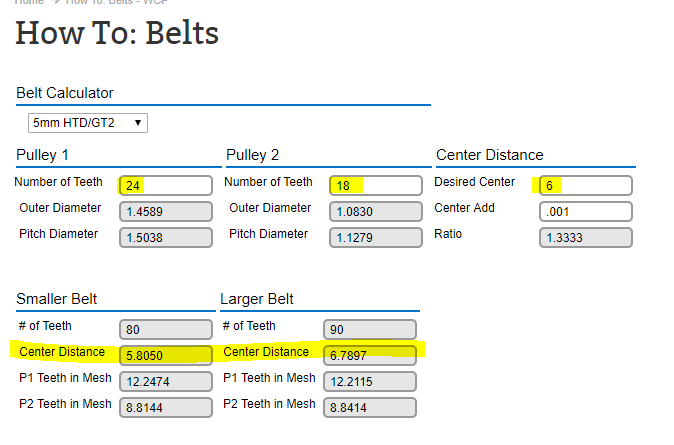
Belt and Pulley
West Coast Products has a great belt and pulley calculator. Make sure you know the number of teeth on each pulley and your desired distance. It will then give you two options – one for a distance smaller than your choice, and one that is bigger.
Snowblower mount for 3d printing
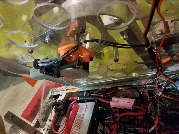
We have lots of these motors. Going to try this type of mount to see how it goes.
https://www.thingiverse.com/thing:2424501
Roboting: A guide for total noobs – really impressed with the quality and presentation of this. Must read for new team members
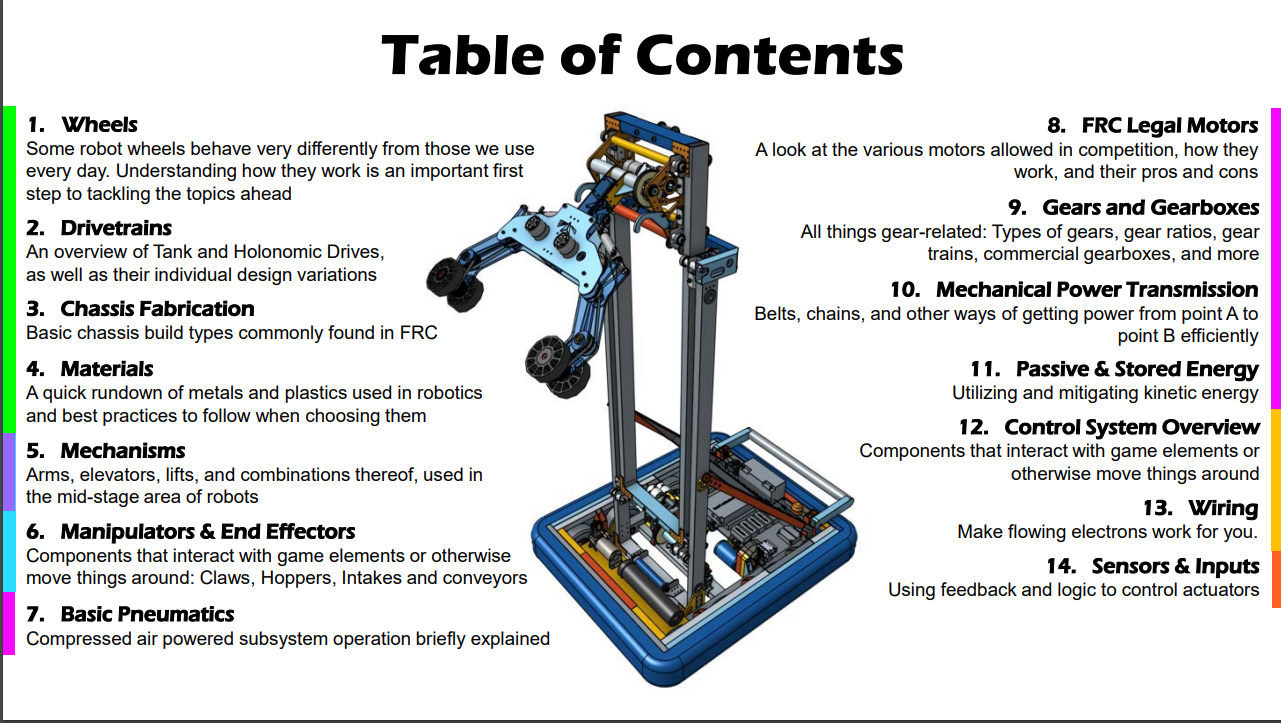
Lots of great information in this resource. New (and experienced) members of our robotics team need to read it.
Tutorial to create a mount for a #redline motor (775 pro) #firstrobotics #frc #inventor @hhs4152 @canfirst #autodesk


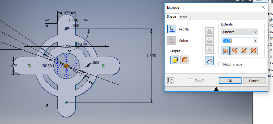
775 pro / redline motors
The 775 pro (or the Andymark knockoff the redline motor) is very useful. I plan to update this page with resources and information. To start off, here is a shield you can 3d print to protect the wires.
Compression rates for ball shooters and pickup mechanisms

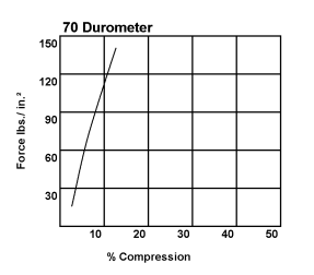 I’ve been trying to find information that will help when designing shooters and loaders. Basically if you have two objects and you know the width of both objects how do you determine the distance between the objects for optimal loading or shooting? Case in point – my class designed some tennis ball shooters and we experimented with different distances because the tennis balls compress. Thankfully our team has built up a collection of different types of wheels so we are able to experiment. The question is can we mathematically determine an optimal distance so that we reduce the number of tests we run. I found this pdf file: http://www.diversifiedsilicone.net/pdf/compression-force-graphs2.pdf. It contains some graphs that show the % compression produced based on the force applied. Next semester we will be trying to make a shooter for the First Steamworks wiffle balls. We know the material that the balls are made of and we have the durometer rates of our various wheels. I’m interested to see if we can design a fairly good shooter using this information.
What’s inside – Victor SP motor controller
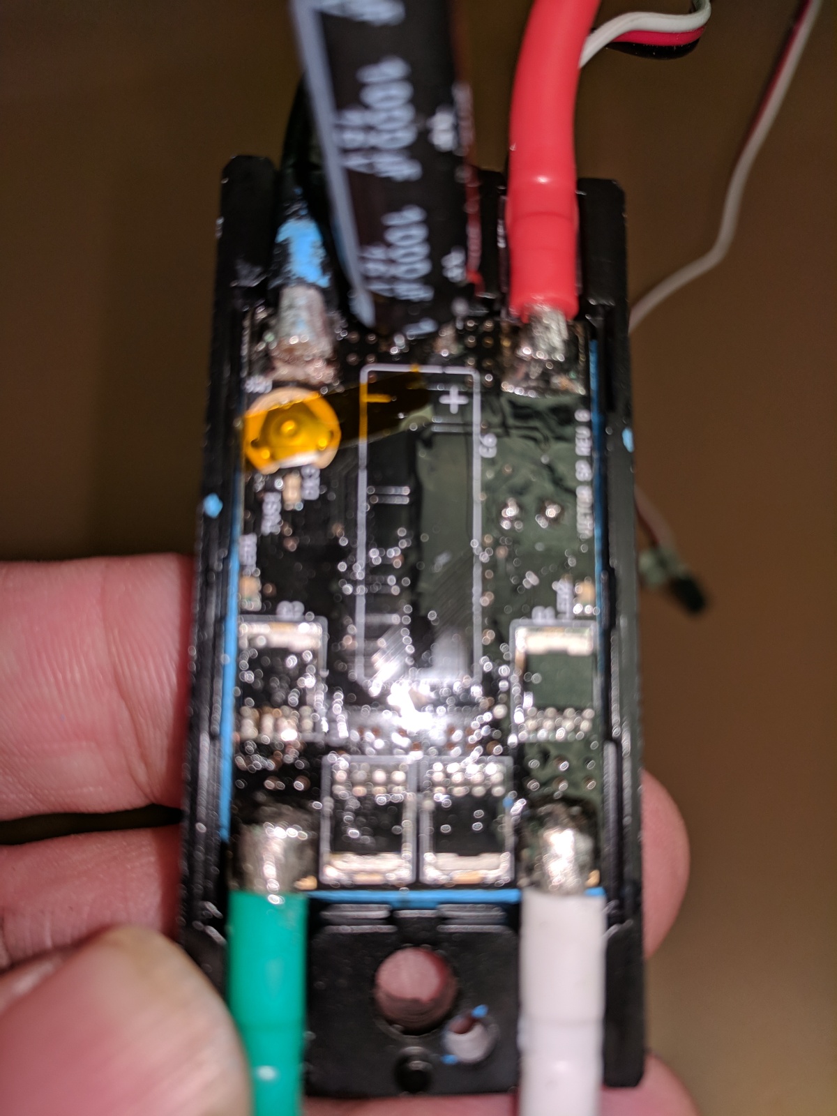
We have a dead motor controller so I took it apart to see what is inside. Here are the photos. I will study this some more. Once another motor controller fries I want to compare them!


Fantastic data on FRC motors: Chief Delphi – Cyber Blue FRC 234 Motor Test Report 12-8-2017
Encoders
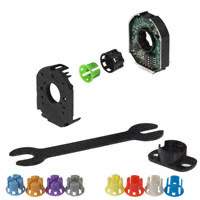 Encoders are sensors used to track the rotations of a wheel. In the 2017 season we used two AMT103-V sensors for our drive train. This allowed us to score gears effectively in autonomous mode as we could determine the number of rotations of the wheels to a great deal of precision. Mounting these encoders was a pain.
We wired the motors with 102-1504-ND connectors. These connectors came loose a few times as they were mounted down and if we ran over a gear they could get caught. We need to look at electrician’s putty which some other teams used.
We are looking at purchasing E4T OEM Encoders. Ideally we would keep six or eight on hand – two for drive train and at least one for any shooting mechanism.

You must be logged in to post a comment.