
Category: Motors
What’s inside a Neo motor?

One of our Neo motors started producing the magic smoke – never a good sign. I opened it up to have a look. We have a CIM motor that we show our students so it is good to be able to examine a brushless motor.

The motor had been mounted with machine screws that were too long. I think they connected with the coils causing a short circuit, heating up and ultimately damaging the motor.
Wiring the #Neo550 motor: tips and tricks @REVrobotics @hhs4152
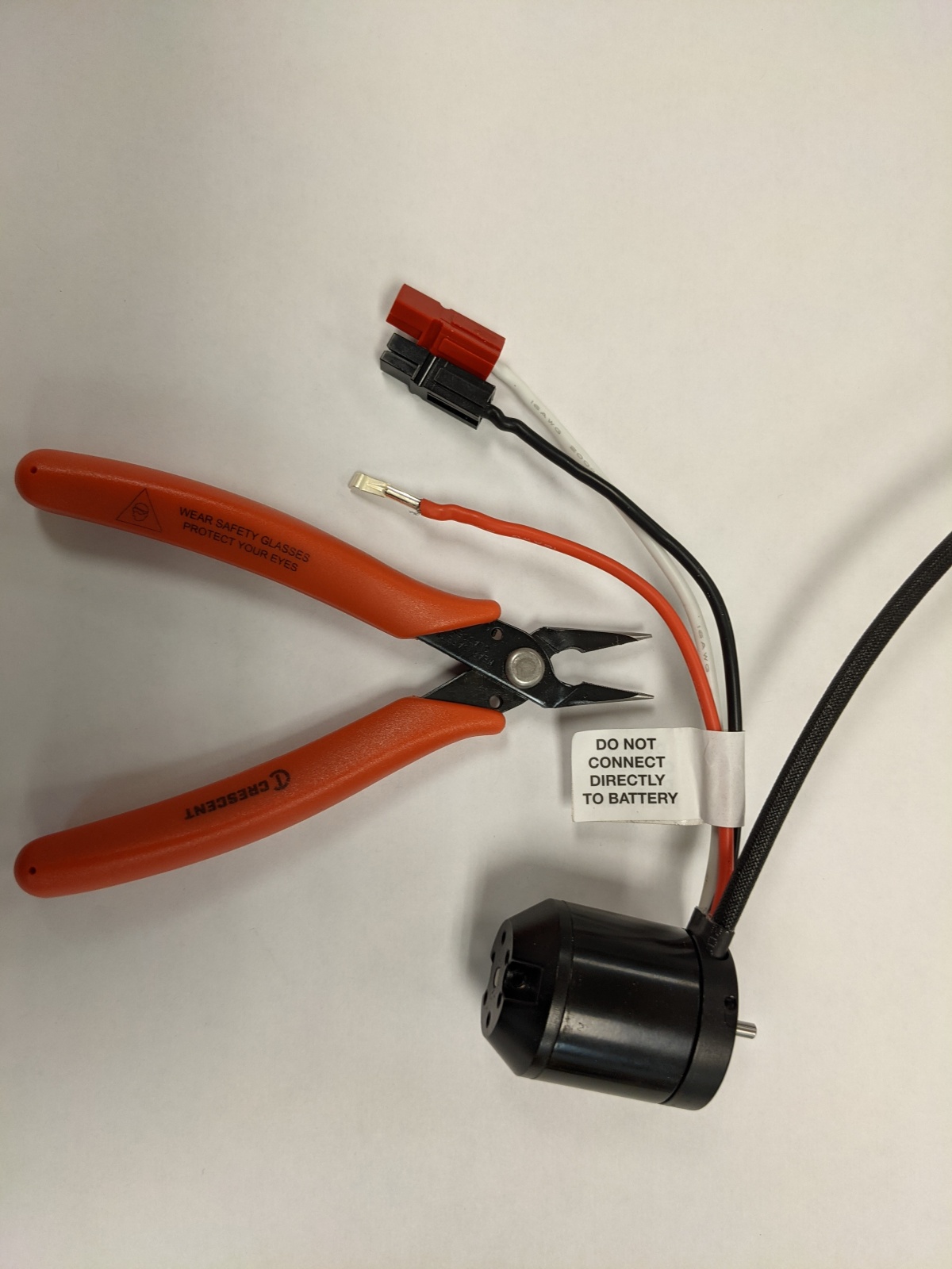
We love using Neo 550 motors – they are small, light and have a ridiculous amount of torque and speed for their size. The challenge is the wiring. The wires are silicone which is very bendy (technical term alert). As with anything, using the right tool makes a huge difference.

Home Depot sells these precision pliers with flush cutters. They are the perfect size to hold onto the metal connector and still fits into the Anderson Powerpole housing.


Using a Neo 550 Motor with VexNet
For a project we are working on we are using the VexNet control system. Neo 550 motors with Versaplanetary gearboxes fit our needs really well so we are working on using them. According to the documentation https://docs.revrobotics.com/sparkmax/feature-description/control-connections you can use PWM to control the Spark Max motor controller. We just did a test using the PWM from the RoboRio and it worked beautifully. The Spark Max needs CAN connector can be plugged into the PWM cable – green to black, yellow to white:

Now that we know this works, we need to finish our Milwaukee Battery adapter to provide a power source. Now we need to test using the VexNet controller.
#Mathteachers – here’s an explanation of how sine waves are used to control brushless motors. Best part – when he uses facial expressions to control the motor!
Using an Arduino to control a Talon or Spark motor controller using PWM

Over the years I’ve accumulated a number of motor controllers from competing in FIRST Robotics. The issue is we only have two RoboRio’s so these motor controllers go unused. My goal is to find a way to control them using an Arduino – this is an inexpensive way to add them to a number of projects.
Resources:
PWM (Pulse Width Modulation) is a common way to control these motor controllers.

I connected a 12v battery to a Power Distribution Panel and used a 40amp circuit breaker for the power connection. The motor connections were to a Redline motor.

The – cable was connecting to GND on the Arduino.
+ was connected to 5V on the Arduino
S was connected to pin 9 on the Arduino.
After installing the PWM library for the Arduino (unzip the folder to C:\Program Files (x86)\Arduino\libraries\PWM) I tried the following code:
https://github.com/IanMcT/ArduinoPWM/blob/master/pwmMcT.ino
Success! the motor spun, stopped and spun some more.

Servo Test Code
With the PWM library it was frustrating trying to determine the settings. I tried using the standard Servo example with the code from the Servo example: https://www.arduino.cc/en/Tutorial/Knob
Instead of using a potentiometer I simply set the variable val to different numbers.
0 – full speed backwards
90 – motor doesn’t turn
180 – full speed forwards.
This method worked really well.
Design a gearbox for #frc using #onshape #firstrobotics

In robotics class we will be doing projects where the ability to design and manufacture a gearbox will be very useful. This tutorial is an adaptation of the tutorial by Ryan Tam:
http://www.team610.com/wp-content/uploads/2014/03/Design-TutorialsRev10.pdf
Future tutorials will be linked to from here showing how to take the design to a complete manufactured part.
In order to complete this tutorial you should learn the fundamentals of parametric design using onShape:
https://learn.onshape.com/learn/learning-path/onshape-fundamentals-cad
You need an education account to access these tutorials.
From Design to Manufacture


Videos of the tutorials:
Parts 1 & 2
Parts 3-5
Parts 6-8
Part 9 – assemble the drive train
Part 9 continued – adding bearings and gears
Designing custom gears
In class we need to work out some gears. I wanted to design my own gear generator in onShape to cement the concepts for myself.

Here is the onShape document I’ve created. It’s a work in progress so it will change over time. The goal is that everything is based on variables:

Change the number of teeth from 36 to 24 and the gear will automatically change.
This document was a great help in working it out.
There’s an online gear generator that is very slick – I’m planning on comparing my gears to it.
Next step – incorporate the Module. For the Denso motor there is a 0.75 module.
https://khkgears.net/new/ is an invaluable resource.
New motor for FRC – Falcon 500
Denso Motors and Ontario Skills

Over the years there have been many Denso motors we received in the Kit of Parts. We’ve not used them due to the lack of power. For Ontario Skills this year we are exploring them
https://www.firstinspires.org/resource-library/frc/mechanical-resources has the link for motor specification:
Using the JVN calculator we are able to determine the RPM for a small robot – note that the units are Oz-In for stall torque!
The module for the gear does not match the gears we get from Vex. This thread provides a link for where we can get CAD files for gears that match.
There are a few teams that have posted gearbox information here.
https://www.thingiverse.com/thing:2016224 is a nice 3d printed gearbox.
We looked at using this. In order to use it in our design we needed to convert the stl files to step files. Once done we ended up with the following:


This has a few issues – the position of the wheel being the biggest. We’re going to look at whether we can re-position items in this gearbox so that the wheel touches the ground and the gearbox is not as bulky.
https://www.team4613.org/redbox the redbox is a smart design.

You must be logged in to post a comment.